I. Product Introduction
It is used to identify a specific cable among a bundle of cables during the installation, relocation, maintenance, and fault handling of power cables. It features accurate and fast cable identification, simple operation, and wide application range. It is an indispensable detection instrument in cable construction and maintenance work.
II. Main Features of the Instrument
This instrument consists of a cable identification transmitter, a cable identification receiver, transmitting clamps, receiving clamps, and output signal connecting wires. It features high-power current pulse output; clear on-site received signal characteristics, lightweight and flexible, high sensitivity, and effective suppression of on-site power frequency interference; accurate and fast judgment; reliable protection circuit, not afraid of output short circuit; large clamp opening of ф125 suitable for power cables of various cross-sections; built-in high-power isolation transformer, ensuring no direct electrical contact between the operator and the mains, greatly ensuring personal safety. When identifying live cables, there is no need to disconnect the connections between both ends of the cables and the power transformation and distribution equipment. Online identification can be performed while the cables are energized, improving identification efficiency and greatly reducing direct and indirect economic losses caused by power outages.
The biggest feature of this instrument is:Unlike conventional identifiers, it adopts the latest communication technology. At the transmitting end, microcontroller technology is used to encode the transmission signal, drive the power, and couple the signal to the cable; the microcontroller in the receiver decodes the received phase-encoded signal and identifies the phase. Based on the uniqueness of the phase characteristics of the signal on the target cable, the target cable is identified from a large bundle of cables. Therefore, the working performance is reliable, and it can accurately identify even ultra-long cables. It is a lightweight, compact, and portable instrument. Suitable for various types of high and low voltage power cables.
III. Brief Introduction to Working Principle
The transmitter and receiver of the Cable Identifier adopt microcontroller encoding and decoding technology and PSK technology widely used in the communication field. A phase-encoded signal with an average value of 0 is transmitted on the transmitting clamp. The microcontroller in the receiver filters the received signal through hardware and software, and then performs phase identification. Point the arrows of the transmitting clamp and receiving clamp toward the cable terminal. When the receiving clamp clamps a certain cable, the ammeter of the receiver deflects to the right, accompanied by audible and visual indication. When clamping other cables, the ammeter deflects to the left, and the current direction is opposite to that of the identified cable, with no audible or visual indication. This reflects the uniqueness of the target cable to be identified, making it easy to clearly distinguish the identified cable from multiple cables. Moreover, since the signal current intensity on the identified cable is the same along the entire line, the electromagnetic signal intensity received by the receiving clamp along the cable is consistent, and the identified cable is not limited by its length.
IV. Instrument Appearance and Function Introduction
(I) The panel of the Cable Identifier transmitter is shown in Figure 3-1:
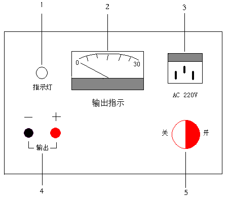
Figure 3-1 Panel diagram of the identifier transmitter
Function Introduction
1. Meter: Indicates the magnitude of the output signal current.
2. Power input socket: Use the dedicated power cord provided with the instrument to input 220V, 50HZ AC power. When using the instrument, it should be plugged into a three-hole power socket independently, and the grounding wire of the socket should be directly grounded nearby. The instrument uses a 5A fuse; if damaged, replace it with a fuse of the same specification.
3. Black binding post: Insert the matching black test lead into this jack, and connect the test clip at the other end to the system ground; Red binding post: Insert the matching red test lead into this jack, and connect the test clip at the other end to the core wire of the cable under test.
4. Power switch: Controls the on/off of the entire instrument's power.
(II) The schematic diagram of the receiver panel is shown in Figure 3-2:
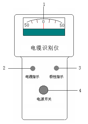
Figure 3-2 Panel diagram of the receiver
(III) Receiver Function Introduction
1. Meter: Indicates the relative magnitude and direction of the received signal current.
2. Indication lamp: When the identified cable is clamped, the lamp lights up; when other cables are clamped, the lamp does not light up.
3. Buzzer: When the identified cable is clamped, the buzzer sounds; when other cables are clamped, the buzzer does not sound.
4. Gain adjustment knob: Adjust the gain of the received signal to make the meter indication clear.
5. Power switch: Controls the on/off of the receiver's power.
6. Power indicator: Lights up when the receiver is powered on.
7. Receiving clamp socket: Connect the receiving clamp to this socket.
V. Usage Methods
(I) Live cable identification (online identification)
1. Connect the transmitter: Connect the black test lead to the black binding post of the transmitter, and the other end to the ground terminal of the cable under test (or the ground terminal of the switchgear); connect the red test lead to the red binding post, and the other end to the core wire of the cable under test. (Note: The cable under test must be a live cable, and the core wire must be a phase wire; do not connect to the neutral wire or ground wire.)
2. Connect the power supply: Plug the power cord into the power input socket of the transmitter, and connect the other end to a 220V AC power source. Turn on the power switch, and the meter on the transmitter panel should indicate a certain current value, indicating that the transmitter is working normally.
3. Connect the receiver: Connect the receiving clamp to the receiving clamp socket of the receiver. Turn on the power switch of the receiver, and the power indicator should light up.
4. Identify the cable: At the other end of the cable under test, clamp the receiving clamp around each cable in the bundle one by one, and observe the meter deflection direction and the indication lamp and buzzer. When the receiving clamp clamps the identified cable, the meter deflects to the right, and the indication lamp lights up and the buzzer sounds; when clamping other cables, the meter deflects to the left, and the indication lamp and buzzer do not respond. In this way, the identified cable can be clearly distinguished from multiple cables.
(II) Dead cable identification (offline identification)
1. Connect the transmitter: Connect the black test lead to the black binding post of the transmitter, and the other end to the ground terminal of the cable under test (or the ground terminal of the switchgear); connect the red test lead to the red binding post, and the other end to the core wire of the cable under test. (Note: The cable under test must be a dead cable, and the core wire must be a phase wire; do not connect to the neutral wire or ground wire.)
2. Connect the power supply: Plug the power cord into the power input socket of the transmitter, and connect the other end to a 220V AC power source. Turn on the power switch, and the meter on the transmitter panel should indicate a certain current value, indicating that the transmitter is working normally.
3. Connect the receiver: Connect the receiving clamp to the receiving clamp socket of the receiver. Turn on the power switch of the receiver, and the power indicator should light up.
4. Identify the cable: At the other end of the cable under test, clamp the receiving clamp around each cable in the bundle one by one, and observe the meter deflection direction and the indication lamp and buzzer. When the receiving clamp clamps the identified cable, the meter deflects to the right, and the indication lamp lights up and the buzzer sounds; when clamping other cables, the meter deflects to the left, and the indication lamp and buzzer do not respond. In this way, the identified cable can be clearly distinguished from multiple cables.
VI. Precautions
1. When identifying live cables, strictly follow the safety operation regulations for live work, and take necessary safety measures.
2. The transmitter must be connected to a power source with a reliable grounding wire; otherwise, it may cause electric shock or damage to the instrument.
3. When connecting the test leads, ensure good contact to avoid poor contact causing heating or affecting the identification effect.
4. During identification, the receiving clamp should be kept perpendicular to the cable as much as possible to reduce interference from other cables.
5. If the meter indication is not obvious, adjust the gain adjustment knob appropriately.
6. After use, turn off the power switches of the transmitter and receiver in time, and properly store the instrument and accessories.
7. The instrument should be kept dry and clean, and avoid vibration and impact during transportation and storage.
VII. Configuration List
1. Cable identification transmitter: 1 unit
2. Cable identification receiver: 1 unit
3. Transmitting clamp: 1 unit
4. Receiving clamp: 1 unit
5. Power cord: 1 piece
6. Test leads (red and black): 1 set each
7. Fuse (5A): 2 pieces
8. Instruction manual: 1 copy
9. Certificate of conformity: 1 copy
10. Packing list: 1 copy


