Insulation Resistance Tester 2500V Megohmmeter Precautions
1. It is forbidden to measure insulation resistance during lightning or near high-voltage equipment. Measurement can only be performed when the equipment is not energized and there is no induced electricity.
2. During the measurement, no one is allowed to work on the equipment under test.
3. The megohmmeter leads must not be twisted together; they should be separated.
4. Before the megohmmeter stops rotating or the equipment under test is discharged, it is strictly forbidden to touch it with hands. When disconnecting wires, do not touch the metal parts of the leads.
5. After measurement, discharge large-capacitance equipment.
Insulation Resistance Tester 2500V Megohmmeter Product Parameters:
Output Voltage 500VDC 1000VDC 2500VDC 5000VDC
Accuracy Temperature 23℃±5℃
Insulation Resistance 1MΩ~20GΩ±5% 2MΩ~40GΩ±5% 5MΩ~100GΩ±5% 10MΩ~200GΩ±5%
Output Voltage 4MΩ~20GΩ0~+10% 8MΩ~40GΩ0~+10% 20MΩ~100GΩ0~+10% 40MΩ~200GΩ0~+10%
High Voltage Short Circuit Current ≥3.5mA
Power Supply 8 AA rechargeable batteries, external charging adapter
Operating Temperature and Humidity -10℃~40℃, max relative humidity 85%
Storage Temperature and Humidity -20℃~60℃, max relative humidity 90%
Insulation Performance When the voltage between circuit and housing is 1000V DC, max 2000MΩ
Withstand Voltage Performance When the voltage between circuit and housing is 2500V AC, withstand for 1 minute
Dimensions 260×200×170mm3(L×W×H)
Product Operation Procedure:
1. Connect the wires according to the four-terminal connection method.
2. Turn on the power.
3. Press the measurement button (if the current display A value is less than 100A, it can be corrected via the panel current fine-tuning).
4. After the measured value is displayed, save the data if needed.
5. After measurement, turn off the power.
6. Please take care of the test clips.
Operation Method:
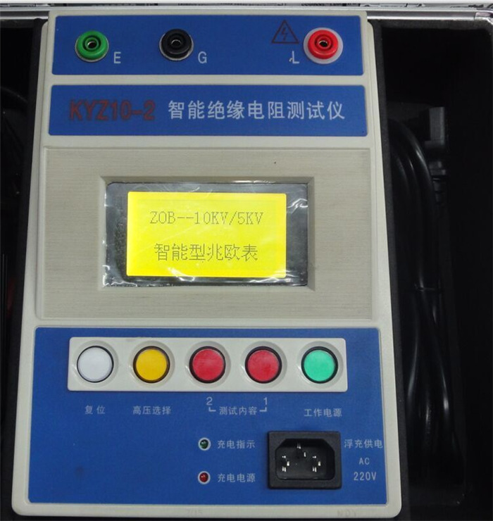
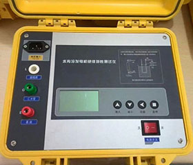
1. Turn on the power switch "ON", select the desired voltage level, lightly press the indicator light to confirm the selected voltage gear, lightly press the high voltage start/stop button, the high voltage indicator light will turn on, and the stable value displayed on the LCD is the measured insulation resistance value. To turn off the high voltage, simply press the high voltage start/stop button once. To turn off the entire device, press the "OFF" button once.
2. When measuring insulation resistance, first disconnect the test object from other power sources, short-circuit and discharge, then connect the dedicated test leads provided with the instrument in sequence as shown in the figure. Insert the red test lead into the "E" terminal of the instrument, and connect the other end to the grounding point or housing of the test object. Insert the white core wire of the black shielded wire into the "L" terminal of the instrument, and connect the other end to the conductive part of the test object that is insulated from the ground. If a guard ring is needed, insert the black core wire of the black shielded wire into the "G" terminal of the instrument, and connect the other end to the shielded part of the test object or the part not involved in the measurement. (Note: During measurement, due to the polarization phenomenon of the insulating material, the insulation resistance reading may drift or fluctuate, which is normal.)
When measuring the insulation resistance between components of electrical products, the "L" and "E" terminals can be connected to any set of lines. For example, when measuring the phase-to-phase insulation of a motor, the three groups can be swapped in turn, and the unused phase should be safely grounded.
3. After starting the high voltage, the built-in timer starts working. At one minute, the instrument automatically alarms for 5 seconds, and the value is locked at this time to facilitate the calculation of the absorption ratio. (After that, it alarms every 45 seconds).