Instructions for Using an Insulation Resistance Tester


 I. Overview


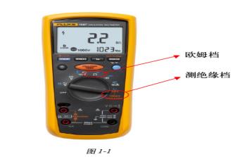
  When debugging AC drive systems, it is necessary to use an insulation resistance tester to perform insulation tests on the main circuit and control circuit of the frequency converter and motor separately, thereby ensuring the safe operation of the system. The Fluke 1587 insulation resistance tester (Figure 1-1) not only provides fast measurement of the main circuit but also offers a 'resistance range' function for insulation testing of the control circuit.


  II. Testing Insulation


  1) When using the Fluke 1587 insulation resistance tester to measure the insulation of the frequency converter main circuit (using VACON NXP products as an example), follow these steps:


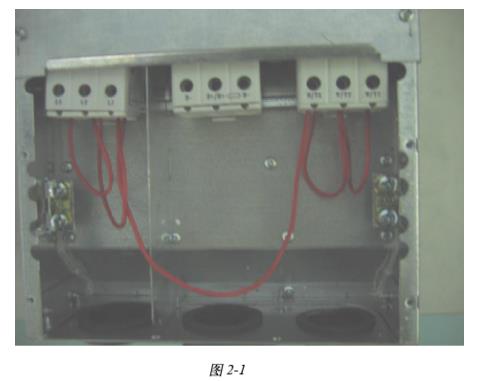
  1. Disconnect all external wiring from the frequency converter, ensuring that the circuit under test is not connected to any power source. Then short-circuit the input terminals L1, L2, L3 and the output terminals U, V, W together, as shown in Figure 2-1.


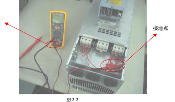
  2. Insert the test probe of the Fluke insulation resistance tester into the '+ input terminal, then connect the other end to the 'ground point' as shown in Figure 2-2.


  3. Connect the probe to the circuit under test. The insulation resistance tester will automatically detect whether the circuit is energized. If the voltage in the circuit exceeds 30 Vac, the test is automatically disabled.


  4. Select the 'Insulation test' function on the Fluke 1587 insulation resistance tester.


  5. Use the 'Range' button to select the appropriate test voltage (500 Vdc).
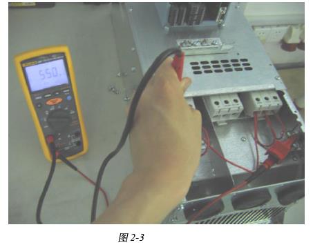


  6. Press and hold the 'Insulation test' button, then read the impedance value displayed on the insulation resistance tester. It may take a few seconds for the reading to stabilize. The higher the impedance value, the better. At this point, the reading is 550 megohms, indicating good insulation. As shown in Figure 2-3.


  7. Keep the probe of the insulation resistance tester on the test point, then release the 'Insulation test' button. The circuit under test will begin to discharge through the meter until complete.


  2) When measuring the insulation of the frequency converter control circuit (using VACON NXP products as an example), note that you must use the 'resistance range' function of the Fluke 1587 insulation resistance tester for continuity testing. Generally, a test value >= 1 megohm indicates good insulation.


  3) When using the insulation resistance tester to test motor insulation, test the U, V, and W three-phase winding wires relative to the ground wire. Generally, a measurement value >= 5 megohms indicates good insulation