There are various electrical test methods for cable lines currently in use, and different voltage levels and types of power cables require different test methods. This article introduces the test methods for oil-impregnated paper insulated cables, plastic insulated cables, and cross-linked polyethylene cables.
The current electrical tests for cable lines generally include: DC withstand voltage and leakage current tests, power frequency withstand voltage tests, insulation resistance measurement, insulating oil tests, partial discharge tests, 0.1 Hz very low frequency tests, and AC variable frequency resonance tests. At present, the power departments have different test methods and contents for different voltage levels and types of power cable lines.
1 DC withstand voltage test for oil-impregnated paper insulated cables
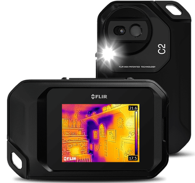
DC withstand voltage reflects the leakage and withstand characteristics of cable insulation.An infrared imager is a portable infrared testing instrument that is compact, lightweight, flexible, and practical. Both theoretical analysis and practical results show that the DC and AC withstand voltage characteristics of oil-impregnated paper dielectric cables, oil-filled cables, or gas-filled cables are essentially the same.
For tests on oil-paper insulated power cables, except for the routine tests conducted by the manufacturer using AC voltage, installation and operation units use DC withstand voltage for acceptance, preventive tests, or post-fault repair tests on cable lines, because DC withstand voltage tests have the following advantages.
a. DC test equipment is portable and suitable for field use. When conducting DC withstand voltage tests on cables, the test voltage is generally obtained through half-wave rectification and multi-stage voltage doubling rectification technology, so test equipment (test transformer and rectifier) with smaller volume and capacity can be used to obtain the DC high voltage required for testing longer cable lines.
b. AC withstand voltage tests may cause free discharge in insulation gaps, leading to permanent insulation damage, while DC withstand voltage tests avoid this situation.
c. During DC withstand voltage tests, leakage current can be measured simultaneously. Based on the value of leakage current and its variation over time, as well as the relationship between leakage current and test voltage, the insulation condition of the cable can be assessed.
d. When conducting DC withstand voltage tests on cables, negative polarity connection is adopted according to regulations, i.e., connecting the conductor to the negative electrode. The advantage of this connection is that if the paper insulation is damp, since water carries a positive charge, under DC voltage there is an obvious "electroosmosis phenomenon" that causes water molecules to move from the surface layer to the conductor (negative electrode), thereby increasing leakage current, even forming a penetrating channel, which is conducive to exposing defects of local dampness in the paper insulation.
e. The voltage application time for DC withstand voltage tests can be relatively short. For example, regulations stipulate that for 6-35 kV cables, the voltage application time for acceptance and preventive tests is 5 minutes per phase. This is because the DC breakdown voltage is not significantly related to the voltage application time; if there are defects, they can generally be detected within a few minutes under DC voltage, without the need for prolonged voltage application.
The voltage standards for DC tests on oil-paper insulated power cables are shown in Table 1. Among them, for tests after cable fault repair and reconnection, 6-35 kV cables follow the preventive test standards, and 110-220 kV cables follow the acceptance test standards; the DC voltage for the outer sheath acceptance test of 110-220 kV cables is 10 kV DC, with a voltage application time of 1 minute.
Measuring leakage current during DC withstand voltage tests is essentially the same principle as measuring cable insulation resistance with a megohmmeter. However, since the applied voltage and the accuracy of the instruments used in DC withstand voltage tests are higher than those of a megohmmeter, and the change in leakage current can be observed during the voltage application process, leakage current tests are more effective than insulation resistance measurements in detecting insulation defects.
Under DC voltage, the current flowing through the cable insulation is the superposition of capacitive current, absorption current, and conduction current. The leakage current flowing through the insulation changes over time and is related to the quality of the cable insulation, the content of impurities, bubbles, moisture, etc.: for cables with sound insulation, as the voltage application time increases, the leakage current decreases and tends to a stable value; for cables with poor insulation, the leakage current quickly tends to a stable value, and the stable value is very close to the initial value; when the insulation has serious defects, the leakage current does not decrease with time but shows an upward trend. If the voltage application time is extended or the DC voltage is increased, the increasing trend of leakage current may continue to develop until insulation breakdown.
In order to make the measured leakage current reflect the true condition of cable insulation, measures should be taken to eliminate the influence of external factors on the leakage current. If the measured leakage current value is unstable, increases with time, or rises sharply with increasing test voltage, the cause must be investigated.
Generally, the ratio of the leakage current measured after the DC withstand voltage test to that measured before the test is called the absorption ratio. The leakage current before the withstand test refers to the leakage current I1 measured 1 minute after the DC withstand voltage test reaches the specified voltage, and the leakage current after the withstand test refers to the leakage current I2 measured when the withstand voltage has lasted for 4 minutes (for 6-35 kV cables) or 14 minutes (for 110-220 kV cables). According to regulations, the acceptance criterion for cable leakage tests is that the absorption ratio I2/I1 ≤ 1.