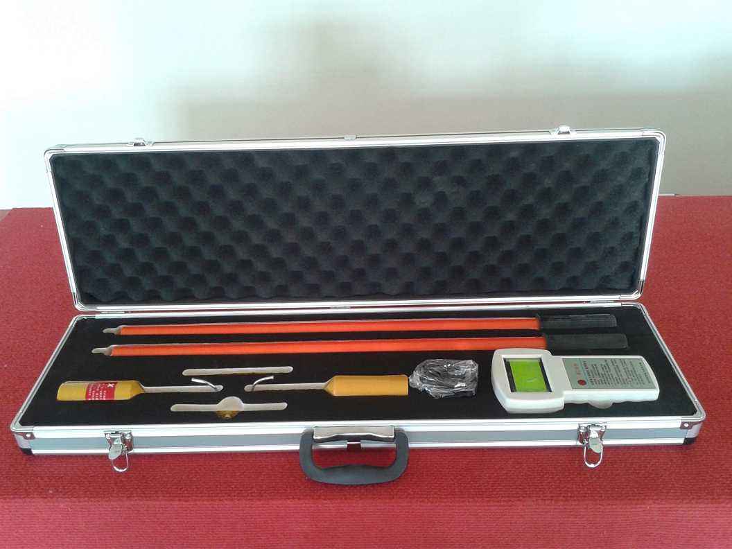
I. Safety Precautions for Wireless High-Voltage Phase Verifier
1. During on-site testing, operators shall operate in accordance with the relevant requirements of the "Safety Work Regulations for Electric Power".
2. The voltage level for which the insulating rods equipped with the wireless high-voltage phase verifier are designed is ≤ 220KV.
II. On-Site Phase Verifier Instructions:
① First, hang the X and Y collectors on the same high-voltage line respectively. The host display should show X and Y in phase, with a phase difference of 355°┉005°.
② When performing phase verification on high-voltage lines, the X and Y collectors should be arranged as follows for phase verification: AA′ in phase 355°┉005°: AB′ out of phase 120° or 240°, BB′ in phase 355°┉005°, BC′ out of phase 120° or 240°, CC′ in phase 355°┉005°.
③ To obtain precise values, keep one collector stationary at a collection point on the high-voltage line, and move the other collector around another collection point on the high-voltage line in all directions, or swap X and Y to find the most accurate phase angle.
④ During phase verification, if the test data for AA′, AB′, BB′, BC′, CC′ all show out of phase, this is because the two groups of power supply lines being tested have different wiring groups, which may result in a phase difference of 30° or 60°. The measurement standard for this situation is described below (using a 30° phase difference as an example): The test method is the same as ① and ②, and the results should be: AA′ out of phase 30°, AB′ out of phase 120° or 240°, BB′ out of phase 30°, BC′ out of phase 120° or 240°, CC′ out of phase 30° (Note: 120° and 240° only indicate positive or negative phase sequence).
⑤ When measuring ≥10KV with the wireless high-voltage phase verifier, X and Y can be directly placed on the conductor or insulating sheath for phase verification.
⑥ When performing phase verification at ≥66KV, the X and Y collectors can use contact or non-contact methods. (For example, when measuring 110KV and 220KV, place the X and Y collectors 300mm to 1000mm below the high-voltage wire. When measuring 500KV, place the X and Y collectors 1000mm-2000mm below the high-voltage wire, with an allowable deviation of 300mm left and right.)
⑦ Measuring phase sequence: Assume a certain line is phase A. Place X on phase A and Y on another phase. If it displays 120°, it indicates a positive phase sequence, and that phase should be "B". If it displays 240°, it indicates a negative phase sequence, and that phase should be "C".
⑧ Voltage detection with the wireless high-voltage phase verifier: Hang one collector on the high-voltage wire. If the host screen displays the symbol of the corresponding collector, it indicates that the high-voltage wire is live. Conversely, if the host screen does not display the symbol of the collector, it indicates that the high-voltage wire is not live (but the collector cannot replace a voltage detector).