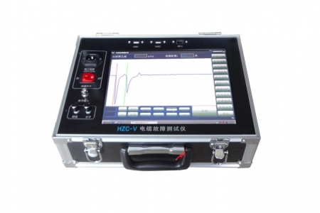
Several Testing Methods for Cable Fault Detectors You May Not Know
Cable fault detector is mainly a testing instrument that promptly locates cable faults, eliminates them as soon as possible, and restores the electrical equipment in the line to normal working condition.
Generally speaking, a cable is a rope-like conductor made of several wires or groups of wires, each group having at least two twisted wires. The groups are insulated from each other and often twisted around a central core, with a highly insulating covering layer over the whole. In power systems, commonly used cables include power cables and control cables. Power cables are used to transmit and distribute large amounts of electrical energy. The following introduces several methods for testing with a cable fault detector.
I. Basic testing methods for cable faults using a cable fault detector
After a cable fault occurs, generally first use a megger or high-resistance meter above 1500V to determine the fault type, then use different instruments and methods for preliminary fault location, and finally use the pinpointing method to accurately determine the fault point. There are two precise measurement methods for the fault point.
One is the acoustic method, whose principle is to use high-voltage pulses to cause discharge at the fault point, producing a discharge sound. A sensor is used on the ground to receive this discharge sound to determine the exact location of the fault point.
Another is the induction method, whose principle is that when an audio-frequency current passes through the cable core, electromagnetic waves exist around the cable. Therefore, carrying an electromagnetic induction receiver and walking along the line, the sound of the electromagnetic waves can be heard. When the audio-frequency current flows to the fault point, the current changes abruptly, and the audio frequency of the electromagnetic waves changes. This method is very convenient for finding low-resistance short-circuit faults between phases, but it is not suitable for finding high-resistance short-circuit and single-phase grounding faults.
II. Specific fault types need to be tested according to the following methods.
1. High-resistance grounding fault: A high-resistance grounding fault in a cable refers to the insulation resistance between the conductor and the aluminum sheath or between conductors being much lower than normal, but greater than 100kΩ, while the core continuity is good.
Testing methods for high-resistance grounding faults:
(1) High-voltage bridge method: Since the resistance at the fault point is large, a high-voltage DC power supply must be used to ensure that the current through the fault point is not too small. The bridge arm resistance is a slide wire resistance of about 3.5Ω divided into 100 equal parts. The voltage applied to the bridge is 10 to 200 kV, and the microammeter indicates 100 to 20 μA. The distance from the fault point to the measuring end can be calculated using the following formula.
(2) One-shot oscilloscope (Type 711) method: The so-called one-shot oscilloscope method uses a high-voltage one-shot oscilloscope to record the discharge oscillation waveform at the fault point to determine the fault point. The distance to the fault point on the oscilloscope screen can be calculated using the following formula: where V is the wave velocity in m/μs; T is the oscillation period in μs.
There are four points to note during measurement: In the same cable, the non-measured cores must also be reliably grounded to prevent dangerous high voltage induced by induction; during measurement, the voltage should be increased gradually. If the ammeter pointer fluctuates or a flashover fault occurs, stop measurement immediately to avoid burning the instrument; since measurement is carried out under high voltage, reliable insulation from ground is necessary. Operators should wear insulating gloves, use insulating rods for operation, and maintain a certain distance from the high-voltage leads; when the positive connection method measurement is completed and wiring needs to be changed, the voltage must be reduced, the power supply cut off, and only after the residual charge in the circuit is fully discharged can the wiring be changed for the reverse connection method measurement.
2. Low-resistance grounding faults: Low-resistance grounding faults are divided into single-phase low-resistance grounding faults, two-phase short-circuit faults, and three-phase short-circuit faults.
(1) Testing the three-phase short-circuit fault point:
When a three-phase short-circuit fault occurs, during measurement, it is necessary to use other parallel lines or install temporary lines as a return circuit. If temporary lines are installed, the resistance of the line must be accurately measured. It can be calculated using the following formula: where R is the single-wire resistance value of the temporary line, and the meanings of the other symbols are the same as in formula (2).
(2) Testing the two-phase short-circuit fault point:
When a two-phase short-circuit fault occurs, during measurement, any faulty core can be used as the grounding wire, and the other faulty core is connected to the bridge. The calculation formula and measurement method are the same as for single-phase low-resistance grounding fault points.
(3) Testing method for single-phase low-resistance grounding fault point:
A single-phase low-resistance grounding fault in a cable refers to the insulation resistance of one core to ground being lower than 100kΩ, while the core continuity is good. This type of fault is highly concealed. We can use the loop pinpointing method principle for testing. Form a measurement loop with the faulty core and another intact core, measure with a bridge, connect one end with a jumper, and connect the other end to a power supply, bridge, or galvanometer. Adjust the bridge resistance to balance the bridge. When the cable core material and cross-section are the same, the following formula can be used for calculation:
If the positions of the damaged core and the good core on the bridge are interchanged, then: where Z is the distance from the measuring end to the fault point in meters; L is the total length of the cable in meters; R1 and R2 are the resistance arms of the bridge.
Under normal circumstances, the measurement results of these two wiring methods should be the same, with an error generally of 0.1% to 0.2%. If it exceeds this range or X>L/2, the measuring instrument can be moved to the other end of the line for measurement.
Notes during measurement: The cross-section of the jumper wire should be close to that of the cable core, and the jumper wire should be as short as possible and maintain good contact. The measurement loop should avoid branch boxes or substations/distribution rooms as much as possible, and the shorter the better. The DC power supply voltage should not be lower than 1500V. The negative pole of the DC power supply should be connected to the cable conductor through the bridge, and the positive pole should be connected to the cable inner sheath and grounded. Operators should stand on insulating pads and place the bridge arm resistance, galvanometer, shunt, etc., on insulating pads.