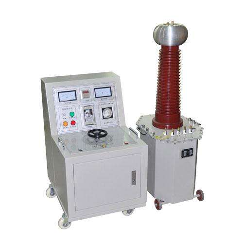
Test transformers utilize advanced production equipment, adopting new processes of coil winding epoxy vacuum casting and CD-type iron cores. Compared with similar oil-immersed transformers, they significantly reduce weight and volume, improve insulation strength and moisture resistance in quality, and effectively weaken magnetic flux leakage, greatly enhancing performance.
In the basic schematic diagram of cascaded test transformers, the low-voltage power supply is applied to the primary winding a1x1 of test transformer I. The output voltage of each single test transformer I, II, and III is V. The excitation windings A1, C1 supply power to the primary winding of the second-stage test transformer II; the excitation windings A2, C2 of the second-stage test transformer II supply power to the primary winding of the third-stage test transformer III.
The enclosures of the second-stage test transformer II and the third-stage test transformer III are respectively at high potentials of 1V and 2V to ground, so the enclosures are insulated from ground, while the enclosure of test transformer I is grounded.