Cascade High-Voltage Test Transformer
Dari Electric recommends:
Short-circuit reactance of auto-coupled cascade transformer
Cascade high-voltage test transformerIf there is a phenomenon of large short-circuit reactance in the test transformer, it will cause a serious reduction in the short-circuit capacity of the test equipment, which in turn will affect the test results of the pollution flashover or wet flashover voltage of insulators. In addition, if the test transformer frequently contacts capacitive loads, when the capacitive current flows through the test voltage regulator and the transformer's short-circuit reactance, the output voltage will exceed the rated values on both sides of the transformer. Therefore, the short-circuit reactance value of the test transformer should not be too large.
(2) Wiring changes can be made to facilitate three-phase testing. Through the implementation of rewiring, transformers can be connected in parallel with each other, thereby supplying large load currents. When the rewiring for three-phase test connections is achieved, the corresponding voltage can be reduced.
(3) If the voltage of the test transformer is required to be at a lower state, only one or two of the transformers can be selected for use, which can effectively reduce the voltage without causing the problem of insufficient excitation of the power generator, and the operation is relatively convenient and simple. Moreover, based on the reduction in the number of cascade transformers, the short-circuit reactance of the loop during the total test process can be effectively reduced.
(4) Due to the structural arrangement, each transformer can also be used independently for its specific purposes, which will increase the number of work sites and scope. Moreover, if one of them fails, it will not affect the normal operation of the whole, effectively reducing losses.
2. Disadvantages of cascade test transformer
(1) The auto-coupled transformer is the most common device in cascade test transformers, so during its operation, the power of the upper-stage transformer needs to be supplied by the lower stage, which results in low overall utilization of the device. Moreover, during insulation operation and treatment, the excitation devices provided by the transformer to each stage will also have low overall utilization due to the insulation effect.
(2) The leakage reactance appearing in the low-voltage winding and excitation winding is mostly caused by phenomena in the insulating transformer. If the number of stages increases, the total reactance will continuously increase or even intensify, so generally the number of cascade stages should not exceed four, but in practical applications this is not effectively achieved.
(3) In a cascade high-voltage test transformer, if overvoltage occurs, the transient voltage between stages may be unevenly distributed, and under certain circumstances, insulation faults such as flashover in the excitation winding or bushing may even occur.
2) The transformer casing and the high-voltage tail must be grounded. To ensure safety, sufficient distance must be maintained between test personnel and other tested equipment and the test transformer.
3) The output of the test transformer should generally be connected in series with a current-limiting resistor to protect equipment safety.
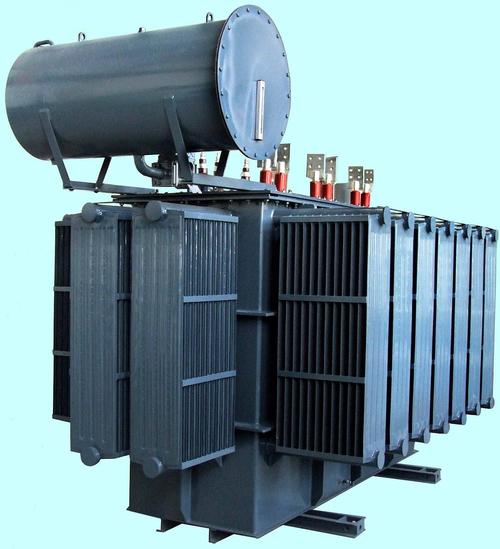
Note: The above information and technical parameters are compiled and released by Yangzhou Dari Electric Co., Ltd.


