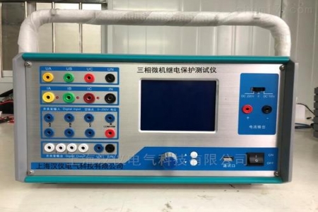
Microcomputer Relay Protection TesterDari Electric recommends:
The microcomputer relay protection tester is a universal test device for relay protection, mainly used for testing and researching various types of protection relays and protection systems of electromagnetic, integrated circuit, and microcomputer types at various voltage levels.
Function
The microcomputer relay protection tester is a universal test device for relay protection, mainly used for testing and researching various types of protection relays and protection systems of electromagnetic, integrated circuit, and microcomputer types at various voltage levels. It can achieve flexible control of voltage and current amplitude, phase, and frequency, and is equipped with special test modules for various relays and protections. It is an essential tool for debugging before commissioning and periodic inspection of protection devices in grassroots power units.
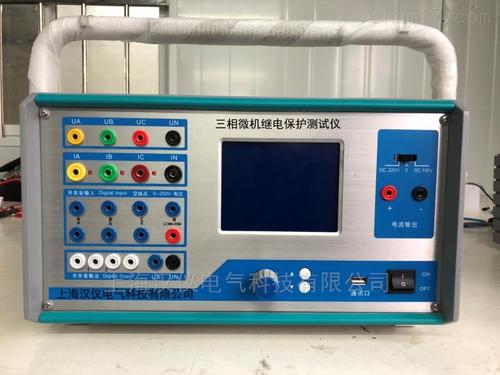
This device is controlled by an embedded industrial computer or an external PC, adopting a single-chassis, modular structure, with an 8.4-inch color LCD display on the panel. It features a graphical window operation interface, easy to operate, with a built-in virtual keyboard, and can be operated only with a mouse. It is equipped with extended parallel port and USB port, can communicate with other PCs, test results can be uploaded or printed online, and software can be upgraded locally through the Internet. With high D/A bits, good current and voltage accuracy, and a power amplifier using direct coupling amplification, it is suitable for both AC and DC, can well simulate the transient process of power systems. The ultra-large current source output power and good wide-band amplitude-frequency characteristics enable it not only to test the characteristics and setting values of various microcomputer protections but also to verify the characteristics and setting values of conventional electromagnetic protections and safety automatic devices. It not only meets the requirements of grassroots power units such as power plants and power supply bureaus for debugging relay protection but is also suitable for research departments and universities to develop and assess various relay protections.
2. Software graphical window operation interface, easy to operate, with a built-in virtual keyboard, and can be operated only with a mouse.
3. Current and voltage amplifier: The current and voltage sources do not use step-up transformers or boosters, but adopt direct coupling amplification. The primary amplification circuit directly receives the signal output from the D/A converter without interpolation processing. This allows the current and voltage to output not only DC and various waveforms from 1 to 1kHz, but also without additional delay, ensuring output response time and correct transient waveforms. When outputting steady-state waveforms, the fast output response ensures the synchronization of current and voltage, as well as the accuracy of phase angle and closing angle.
The power amplification circuit has comprehensive current, voltage, and over-temperature protection functions to prevent damage to high-power devices during testing. When the current source is open-circuited or overloaded, it automatically alarms, the corresponding phase emits an alarm light indication, and there is a continuous alarm sound. When the voltage source is short-circuited or severely overloaded, the power amplifier is tripped, the power indicator light flashes red, and an alarm sound is emitted. To prevent overheating of the current amplifier due to long-term operation under high current, when any phase current of the test device exceeds 10A, the software has a time-limited function. This time limit does not affect normal use, mainly to prevent unreasonable settings or operations by users from causing long-term erroneous output of high current.
4. Power supply: The instrument uses single-phase 220V AC power. When the main power switch on the panel is closed, only ±5V and ±15V voltages are generated for the D/A board, and the panel power indicator lights green. When the power amplifier power switch button is pressed (closed) and the software power amplifier switch is also automatically closed after entering the application, the power amplifier DC power is applied, and the panel power indicator lights red. If any of the aforementioned switches is turned off (soft or hard power amplifier switch), the power amplifier power is disconnected, and the panel power indicator lights green.
5. The power amplifier power supplies for each phase of voltage and current are independent, and the outputs are isolated from each other. The voltage and current of each phase can be flexibly used in series or parallel.
6. The software is programmed in C++, allowing for rapid software upgrades. It is equipped with extended parallel port and USB port. It can communicate with other PCs, and the software can be upgraded locally through the Internet.
7. Test results can be uploaded or printed online, and the report format is compatible with Excel.
8. High-strength anti-vibration aluminum alloy chassis, lightweight, wear-resistant, corrosion-resistant, and impact-resistant.
Note: The above information and technical parameters are compiled and released by Yangzhou Dari Electric Co., Ltd.