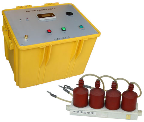
Partial Discharge Detector
Definition and Causes of Partial Discharge
Under the action of an electric field, only part of the insulation system discharges, but it has not yet broken down (i.e., there is no breakdown between the conductors to which voltage is applied). This phenomenon is called partial discharge. Partial discharge may occur adjacent to conductors, on the surface of insulation, or inside the insulation. Discharges on the surface are called surface partial discharges, while those inside are called internal partial discharges. For discharges occurring near conductors surrounded by gas, it is called corona. To summarize, partial discharge is defined as an electrical discharge that partially bridges the insulation between conductors. The main causes of partial discharge are as follows:
Non-uniform electric field.
Non-uniform dielectric.
Bubbles or impurities during the manufacturing process. The most frequent cause of discharge is the presence of bubbles inside or on the surface of the insulation; secondly, during the operation of some equipment, thermal expansion and contraction occur, and since different materials, especially conductors and dielectrics, have different expansion coefficients, cracks gradually appear; thirdly, during operation, organic polymers age and decompose various volatiles. Under high field strength, charges continuously enter the dielectric from the conductors, causing the dielectric to vaporize at the injection points.
Partial Discharge Detector
2. Introduction to the Simulation Circuit and Discharge Process of Partial Discharge
The internal discharge characteristics of a dielectric containing bubbles under AC voltage can be represented by the simulation circuit in Figure 1—1 (equivalent circuit a, b, c); where Cc is the capacitance simulating the discharge gap (such as a bubble) in the dielectric; Cb represents the combined capacitance of the dielectric in series with Cc; Ca represents the capacitance of the rest of the dielectric.
(a) Actual dielectric (b) Simulation circuit
I——Part of the dielectric with defects (bubbles) (indicated by dashed lines)
II——Part of the dielectric without defects
Figure 1—1 Simulation circuit representing internal discharge
In Figure 1—1, the internal bubble that generates partial discharge is simulated by a capacitor Cc in parallel with a pair of spark gaps. Figure 1—2 shows the occurrence process of partial discharge under AC voltage.
Figure 1-2 Partial discharge process of a single bubble inside a dielectric under AC voltage
U(t) - Applied AC voltage
Uc(t) - Voltage across the bubble when it does not break down
Uc’(t) - Actual voltage across the bubble during partial discharge
Vc - Breakdown voltage of the bubble
Vr - Residual voltage of the bubble
Us - Partial discharge inception voltage (instantaneous value)
Ur - Applied voltage corresponding to the residual voltage Vr of the bubble
Ir - Discharge current in the bubble
Total capacitance between electrodes Cx = Ca + (Cb × Cc) / (Cb + Cc) = Ca. When an AC voltage u(t) is applied between the electrodes, the corresponding voltage across the bubble capacitance Cc is Uc(t). As shown in Figure 2—1, Uc(t) represents the voltage in the ideal state of the bubble (i.e., the bubble does not break down).
Uc(t) = U(t) × Cb / (Cc + Cb)
When the applied voltage U(t) rises, the voltage across the bubble Uc(t) also rises. When U(t) rises to Us, the voltage across the bubble Uc reaches the breakdown voltage of the bubble, the bubble breaks down, generating a large number of positive and negative ions. Under the action of the electric field, they migrate to the upper and lower walls of the bubble, forming a space charge, establishing a reverse electric field, weakening the total electric field strength inside the bubble, causing the discharge to extinguish, and the bubble recovers its insulation performance. The duration of such a discharge is extremely short; for a typical air bubble, it is only about a few nanoseconds (10 to the power of -8 to 10 to the power of -9 seconds).