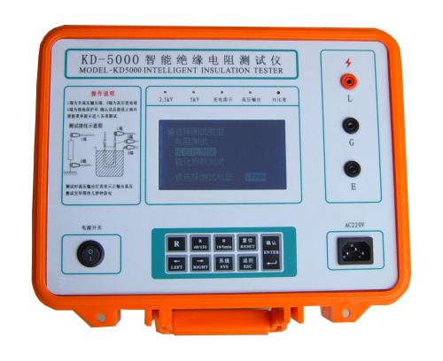
The first is the DC high voltage generator, used to generate a DC high voltage.
The second is the measurement circuit.
The third is the display.
(1) DC High Voltage Generator
To measure insulation resistance, a high voltage must be applied to the measurement terminals. This high voltage value is specified in the national standard for insulation resistance meters as 50V, 100V, 250V, 500V, 1000V, 2500V, 5000V…
There are generally three methods to generate DC high voltage. The first is the hand-cranked generator type. About 80% of the megohmmeters produced in China use this method (the source of the name "megger"). The second is to step up the voltage through a mains transformer and rectify it to obtain DC high voltage. This is generally the method used by mains-powered megohmmeters. The third is to use a transistor oscillator or a dedicated pulse-width modulation circuit to generate DC high voltage, which is generally the method used by battery-powered and mains-powered insulation resistance meters.
(2) Measurement Circuit
In the aforementioned megger (megohmmeter), the measurement circuit and the display part are combined into one. It is accomplished by a ratio meter head, which consists of two coils with an angle of about 60° between them. One coil is connected across the voltage terminals, and the other coil is connected in series in the measurement circuit. The deflection angle of the meter pointer depends on the current ratio in the two coils. Different deflection angles represent different resistance values. The smaller the measured resistance, the greater the current in the coil connected in series in the measurement circuit, and thus the larger the deflection angle of the pointer. Another method is to use a linear ammeter for measurement and display. In the ratio meter head used earlier, due to the non-uniform magnetic field in the coil, when the pointer is at infinity, the current coil is exactly at the place with the strongest magnetic flux density, so even if the measured resistance is large and the current flowing through the current coil is very small, the deflection angle of the coil will be relatively large. When the measured resistance is small or zero, the current flowing through the current coil is large, and the coil has already deflected to a place with lower magnetic flux density, so the resulting deflection angle will not be very large. In this way, nonlinear correction is achieved. Generally, the resistance display of a megohmmeter head needs to span several orders of magnitude. However, when a linear ammeter head is directly connected in series in the measurement circuit, it will not work; the scale at high resistance values is all squeezed together and cannot be distinguished. To achieve nonlinear correction, nonlinear elements must be added to the measurement circuit, thereby producing a shunting effect at small resistance values and no shunting at high resistance values, so that the resistance display can span several orders of magnitude. With the development of electronic technology and computer technology, digital display meters are gradually replacing pointer-type instruments.
Digital measurement technology for insulation resistance has also been developed, among which the voltage ratio meter circuit is one of the better measurement circuits. The voltage ratio meter circuit consists of a voltage bridge circuit and a measurement bridge circuit. The signals output by these two bridge circuits are respectively converted through A/D conversion and then converted by a microcontroller into digital values for display.
Note: The above information and technical parameters are compiled and published by Yangzhou Darui Electric Co., Ltd.