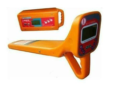
Underground Pipeline Detector Operation Manual
GXY-2000Underground Pipeline DetectorTransmitter has three working methods for applying signals: Direct Connection, Coupling, and Induction. The GXY-2000Pipeline DetectorReceiver also has three working modes: Peak, Null, and A-frame. The following descriptions assume the receiver is in Peak mode. I will give a brief introduction below.
1 Direct Connection Method:
Direct connection involves directly applying the transmitter's signal to the pipeline under test. When using this method to locate the target pipeline, two frequencies on the transmitter can be used: Audio and Radio. The difference is that the audio signal has a lower frequency, attenuates slowly, and travels longer distances; it has weaker radiation and penetration, making it less prone to cross-talk. The radio signal has a higher frequency, better penetration and radiation, but contains more high-frequency components, attenuates faster, and has a shorter transmission distance. When locating, these two frequency characteristics should be flexibly applied.
During use, if the far end is grounded and the loop resistance is low, use the audio frequency to locate the target pipeline. When the loop resistance is high, try to improve the grounding condition to reduce it. If the far end cannot be grounded due to certain restrictions, or the loop resistance remains high after grounding treatment, or there are joints, insulation, etc. in the pipeline, then the radio frequency signal should be used. (If the transmitter shows a loop resistance greater than 2000, it indicates the loop resistance is somewhat high.)
2 Coupling Method:
Sometimes, due to environmental or situational constraints (e.g., live cables), the signal cannot be directly applied to the target pipeline. In such cases, this method is used. The transmitter applies the signal to the pipeline under test via a coupling clamp. Users must ensure the clamp jaws are fully closed and use the audio frequency. Since this frequency has weaker penetration, the loop resistance must be low, requiring both ends of the target pipeline to be grounded. Before locating, the user should determine whether both ends of the target pipeline are grounded, or if there are joints or insulation in between. When choosing the clamp placement point, avoid placing it at the pipeline ends; keep it as far away from the ends as possible.
3 Induction Method:
This method can only use the radio frequency signal because it has wide radiation and strong penetration. When using it, first adjust the distance between the transmitter and receiver, because in this method, the transmitter emits a planar radio frequency signal, so the air also contains the signal. To prevent the receiver from directly picking up the airborne signal, the distance between them must be adjusted. This can be done by controlling the distance and the receiver's gain.
When locating, if the target is a single pipeline, start from the pipeline's end. If environmental constraints or special circumstances exist, find an obvious exposed point in the middle, such as a manhole cover. Note that the transmitter should be placed directly above the target pipeline along its direction to maximize the applied signal. Then use the receiver in radio frequency mode to detect the signal from the target pipeline.
For large-area surveys, the transmitter and receiver should be moved in parallel, maintaining the distance between them and advancing synchronously. This is what we call "sweeping."
4 50Hz Method
This method can be used to locate live cables. It is simple, requiring only the receiver; set the receiver frequency to 50Hz.
The GXY-2000 pipeline detector has three depth measurement methods: Direct Read, 45-Degree, and 80% Method.
During depth measurement, if the signal is directly applied (i.e., under direct connection), the Direct Read method can be used. For accurate depth measurement, the choice of location is crucial. The test point should be on a straight section of pipeline with no branches, joints, or interference from adjacent pipelines. This method has limitations. The 45-Degree method involves placing the receiver directly above the target pipeline, then rotating it 90 degrees in place, and moving the receiver perpendicular to the pipeline direction until the signal is at its minimum. The distance from this point to the maximum signal point is the burial depth. The angle in the 45-degree method is difficult to control, limiting its application. Now I will describe the 80% method. This method is not restricted by the connection type and is simple and intuitive. In summary, after the transmitter emits a signal, the receiver finds the maximum signal point above the pipeline and records the signal strength at that point as Xmax. Then, moving perpendicular to the pipeline on both sides, when the signal strength drops to 80% of Xmax, mark these two points. The distance between these two points is the burial depth of the pipeline.
Note: When measuring depth, the receiver must be in Peak mode.