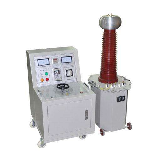
YHJB-A Single-phase Relay Protection Calibration
YHJB-A Single-phase Relay Protection Calibration Tester can independently provide DC voltage, DC current, AC voltage, AC current, or simultaneously provide DC voltage and DC current, and also provide millisecond meter synchronous timing measurement. It is suitable for measuring the opening and closing time of single-circuitdry contacts and live contacts, positive and negative pulse width measurement, action and return voltage (current) measurement, dual-channel signal time interval measurement, and whole group testing.
Product Features of Single-phase Relay Protection Calibration Tester
Product Characteristics
1. The device weighs 10 kg with the same main body, adopts stainless steel or plastic-aluminum case, which is beautiful and sturdy with good shock absorption performance.
2. It adopts a dual carbon brush voltage regulator (i.e., double-sided voltage regulator). The large knob adjusts the AC/DC voltage and current with heavier load, while the small knob adjusts the AC/DC voltage and current with lighter load. Both circuits can output simultaneously.
3. It adoptsa 0.5-class digital meter and high-precision sensor for accurate measurement. It uses a six-digit digital electric stopwatch to meet time measurement requirements. It is truly a good tool for relay protection staff working outdoors.
Technical Parameters:
1. Input Power: AC220V±10% 50Hz
2. Nominal Capacity: 0.75KVA (capacity can be increased or decreased as required)
3. Output:
Main Circuit: AC 0-250V (3A)
(Adjusted by large knob) 0-500mA (15V) with series resistor
0-10A (15V) with series resistor
0-100A (10A)
DC 0-350V (3A)
0-500mA (15V) with series resistor
0-10A (15V)
Auxiliary Circuit AC 0-20V (1A)
(Adjusted by small knob) AC 0-250V (1A)
DC 0-350V (1A)
4. Measurement Range:
Voltage Measurement Range: 0-500.0V (direct measurement)
AC Current Measurement Range: 0-500mA (direct measurement)
0-10.00A (sensor input)
0-100.0A (sensor input)
DC Current Measurement Range: 0-500.0mA (DC)
0-10.00A (shunt input)
Time Measurement Range: 0-999.999S (resolution 1mS)
5. Accuracy: Measurement accuracy is 0.5 class
6. Dimensions: 272mm×172mm×262mm
7. Weight: 10kg
8. Operating Ambient Temperature: -20℃-45℃
Working Principle:
Principle Description
The instrument is divided into two circuits: main circuit and auxiliary circuit. The main circuit is adjusted by the large knob, and the auxiliary circuit is adjusted by the small knob. The main circuit controls various output quantities through the "Output Selection" push button switch on the panel. Each time a different output is switched, the digital voltage/current meter on the instrument can automatically monitor its output value. The auxiliary circuit directly adjusts the output through the output switch control, and measurement can be performed with an external multimeter.
Main Circuit Principle
The input AC220V power supply enters the input end of the dual carbon brush voltage regulator T1 through the fuse and output control relay K1. The electricity adjusted by the large knob of T1 enters the isolation transformer T2 (also serving as a current booster). The current booster has three tap outputs. One tap is AC0-250V output with a rated current of 3A; the output voltage of this tap can be rectified and filtered to output 0-350V DC voltage. The second tap is 15V (10A). One path of this tap outputs 0-10A AC current through the sensor and relay control, another path outputs 0-500mA AC current through a resistor, and another path can output 0-10A or 0-500mA DC current through relay switching. The third tap is the 10V (100A) high current terminal. This tap passes through the primary side of the sensor and directly outputs 100A current. This circuit has strong load capacity, but the output is slightly overloaded and cannot be in a high current state for a long time.
Auxiliary Circuit
Similar to the main circuit, the AC220V power supply enters the voltage quantity adjusted by the small knob of the dual carbon brush voltage regulator T1 through the fuse. Through the isolation transformer T4, it can directly adjust the output of 0-20V or 0-250V AC voltage or 0-350V DC voltage. The rated current of this circuit is 1A. Press the "Output Control" switch of the auxiliary circuit and adjust the small knob to output.
Measurement Circuit
The main circuit output quantities adjusted by the large knob include AC "0-250V", "0-500mA", "0-10A", "0-100A", and DC "0-350V", "0-500mA", "0-10A". Through relay switching on the circuit board inside the device, each time a gear is switched, the corresponding output quantity can be monitored. Among them, the "0-500mA" gear is included in the "0-10A" gear. When in use, the position two below "0-10A" is the "0-500mA" monitoring.
Time Measurement
The device has a built-in 6-digit digital stopwatch. The electric stopwatch can be started internally or externally. For internal start, press the "Output Control" switch to start the stopwatch, and short-circuit the stop terminals on the device panel to stop the stopwatch. The stopwatch has a separate power switch, and it can be turned off when not in use.
Audible and Visual Indication
The circuit device has a built-in audible and visual indication circuit. When the contacts of the relay under test operate, the contacts can be connected to the audible and visual indication jack of the test box. The test box will emit an alarm sound or light to indicate the contact operation status of the relay.
Precautions:
1. Before powering on, no load should be connected to any output terminal, the voltage regulator should be at zero position, and the "Output Control" switch should be in the OFF position.
2. The voltage output terminal should not be connected with low-resistance load to avoid overheating due to overcurrent.
3. Only one type of quantity can be output from the auxiliary circuit and the main circuit at a time.
4. When the auxiliary circuit and the main circuit output simultaneously, the main circuit output current should be selected.
5. During storage, transportation, and use, attention should be paid to shockproof, moisture-proof, avoiding severe impact and drop damage.
Dari Electric After-sales Service System:
1. Our company has a professional after-sales service team, and the after-sales service department is led by the vice president in charge of sales.
2. The after-sales service department currently has 10 staff members, ensuring timely maintenance of our company's products.
3. Our after-sales service goal is: to promptly solve on-site equipment failures, respond quickly, and provide the best service!