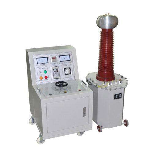
Power Frequency Withstand Voltage Test Device
TPSBJ AC Test Transformer is a single-phase transformer with connection group label II. The working process of a single test transformer is as follows: AC 220V voltage (380V for above 10KVA) is connected to the power control box (console), and through the auto-transformer (external for above 50KVA) inside the power control box (console), the voltage is adjusted to 0~200V (0~400V for above 10KVA) and applied to the primary winding of the test transformer. According to the principle of electromagnetic induction, the high voltage required for the test can be obtained on the high-voltage winding of the test transformer.
DC Leakage Test
1. Before testing the test object, all external connections should be removed, and it should be fully discharged. The main parts should be cleaned and kept absolutely dry to avoid damaging the test object and causing errors in test values.
2. For large-capacity test objects (capacitors, extra-long cables, etc.), the voltage should be raised slowly during the test to prevent the charging current of the test object from being too large and burning out the microammeter. If necessary, the voltage should be raised in stages and the stable readings of the microammeter at each voltage level should be recorded separately.
3. During the test, the test object, microammeter, and test device should be closely monitored. Once phenomena such as flashing or breakdown occur, the voltage should be immediately reduced, the power should be cut off, and the cause should be investigated.
Power Frequency Withstand Voltage Test
1. Test personnel should divide responsibilities clearly, set up the safety distance at the test site, carefully check the grounding of the test object and the test transformer, and arrange dedicated personnel to monitor safety and observe the status of the test object.
2. The main parts of the test object should be cleaned and kept absolutely dry to avoid damaging the test object and causing errors in test values.
3. For tests on large equipment, a no-load test of the test transformer should generally be conducted first, that is, raising the voltage to the test voltage without connecting the test object, in order to calibrate the indication accuracy of the instruments and adjust the gap distance of the discharge ball gap.
4. During the withstand voltage test, the voltage raising speed should not be too fast, and sudden pressurization should be prevented, such as sudden closing when the voltage regulator is not at zero position. Sudden power off should also be avoided; generally, the switch should be opened after the voltage regulator is reduced to zero.
5. During the voltage raising or withstand voltage test, if any of the following abnormal conditions are found: (1) the pointers of the voltmeter and ammeter swing greatly, (2) the test object emits abnormal sounds, (3) the insulation shows signs of burning or smoking, the voltage should be immediately reduced, the power should be cut off, the test should be stopped, and the cause should be investigated.
6. When using this product for high-voltage tests, in addition to being familiar with this manual, the relevant national standards and operating procedures must be strictly implemented. Reference can be made to GB311-83 "Preventive Test Procedures for Electrical Equipment" and other standards.
Edit this section
Test Transformer
The rated voltage on the high-voltage side should not be less than the maximum test voltage of the test object, and the rated current should not be less than the maximum capacitive current of the test object. The calculation formula for the capacitive current of the test object and the required capacity of the test transformer is:
I = 2π f Cx U × 10 -6
U I = 2π f Cx U 2 × 10 -9
Where I - capacitive current of the test object, A; f - power frequency, Hz;
Cx - capacitance of the test object, μF; U - effective value of test voltage, V
Se - required rated capacity of the test transformer, KVA
The capacitance Cx of the test object can be measured by an AC bridge. The capacitance of common test objects is selected according to Table 1.
Capacitance of Several Common Test Objects (pF)