

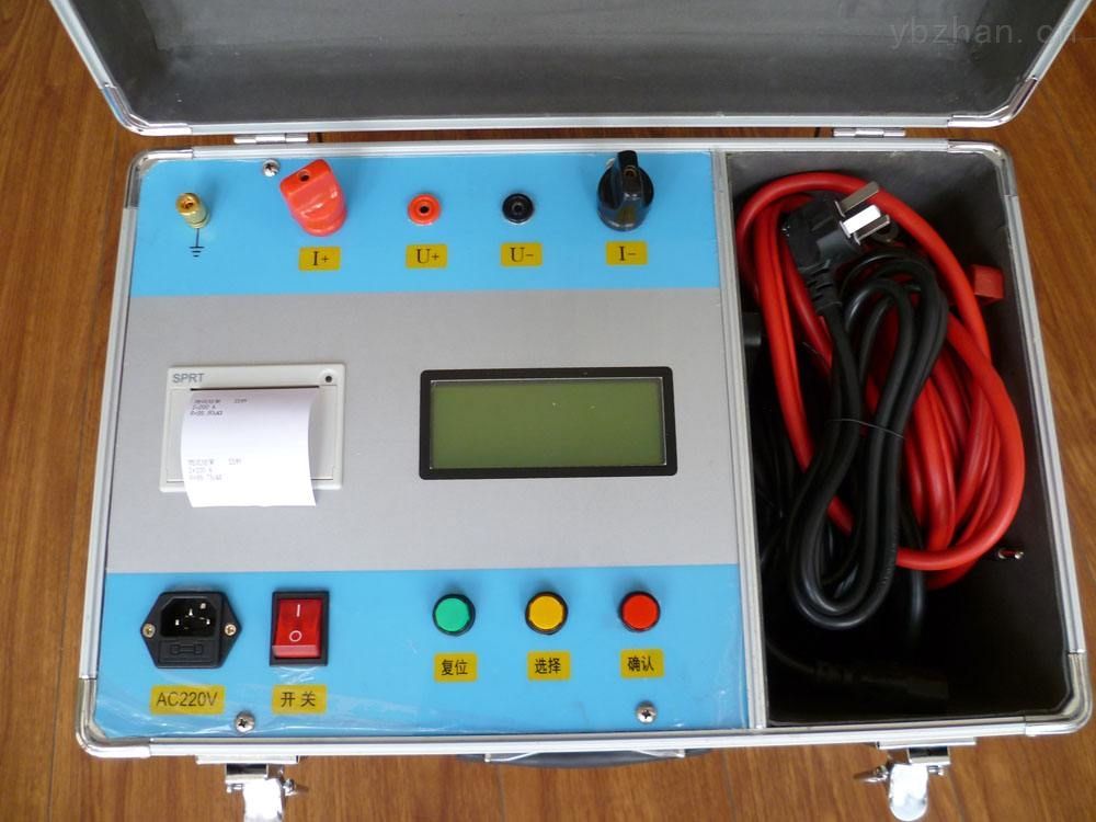
Currently, most loop resistance testers on the market operate on the principle of the typical four-wire measurement method. A high-frequency switching power supply provides a test current greater than 100A. When the measurement button is pressed, the high-frequency switching power supply outputs a test current above 100A, and the sampling circuit begins sampling. The acquired signal is amplified by an amplifier, converted from analog to digital by an A/D converter, and then processed by a microprocessor for filtering, calculation, and processing before being displayed on the screen as the current and resistance values. If the current test loop experiences a disconnection or poor contact, the instrument can determine based on the voltage across the current shunt that the current loop has poor contact or is open. The DC resistance tester adopts new power supply technology, featuring rapid measurement, compact size, ease of use, and high measurement accuracy. It is an ideal device for measuring the DC resistance of transformer windings and high-power inductive equipment.
1. Problems with Existing Testing Methods
Loop resistance testers designed according to conventional principles have been found to commonly exhibit a problem during field testing: when the voltage measurement loop of the tester has poor contact or is open, the tester still displays a value. In such cases, the following situations may occur:
(1) If the voltage loop is open and there is no strong electric field interference at the test site, the differential mode voltage input to the amplifier is essentially zero, so the displayed test value is close to zero. If the tester has sufficient field experience, they can determine that the voltage loop test leads are abnormal, and after troubleshooting, obtain correct results. However, if the tester lacks experience, they might mistakenly conclude that the tester is faulty, interrupt testing, replace or repair the instrument, delay power outage time, and cause unnecessary complications.
(2) In the case of poor contact in the voltage loop, most circuit breaker terminals develop an oxide film or oil film on the outer surface of the terminal block after prolonged operation. When the voltage test clips of the loop resistance tester are attached to such terminals, poor contact may occur. Additionally, the voltage test leads themselves introduce a certain contact resistance. When this contact resistance becomes comparable to the internal resistance of the voltage sampling loop, it can severely affect the test results.
(3) If the voltage loop is open or has poor contact (open circuit can be considered as infinite contact resistance R1), and there is strong electromagnetic interference at the test site, such as when the busbar is energized, the energized busbar can interfere with the two voltage test leads through the air dielectric capacitance, causing a differential mode voltage to appear across the voltage sensing leads of the tester.
If the interference is significant, the loop resistance tester may display a value much larger than the actual resistance of the test object. In this case, an experienced tester might recognize the abnormal result and take note to obtain correct measurements. However, if the tester lacks experience, they might mistakenly conclude that the switch loop resistance exceeds the standard, potentially leading to unnecessary outage maintenance and causing avoidable losses in power production.
If the interference is not very strong, the displayed value might fall within the acceptable resistance range for the circuit breaker. This situation yields the same result as case "(2) Poor contact in the voltage loop," leading to misjudgment.
2. Solving the Above Problems with an Improved Four-Wire Measurement Method.
Based on the analysis of the above issues, the YTC5501 loop resistance tester proposes an improved four-wire measurement method. It utilizes power supply technology that can continuously output high current for extended periods, overcoming the drawbacks of instantaneous current in pulse-type power supplies. This effectively breaks through the oxide film on switch contacts and resolves the problems existing in traditional loop resistance testers.
By applying a high-current constant current source to energize the test object and measuring the voltage and current values, the resistance of the test object is calculated. The measured value is guaranteed to be the true resistance of the test object, eliminating the generation of false data. Even if there is strong electric field interference at the site, since the resistance in the voltage loop is very small, the voltage induced at the voltage sensing terminals is common-mode voltage. This product reduces this AC common-mode interference to a very low level through capacitive grounding, ensuring no impact on measurement accuracy.
The above demonstrates that the automatic judgment and indication functions greatly enhance testing accuracy and improve production efficiency, serving as a reliable aid for field test personnel to quickly resolve issues.
Parameters of YTC5501 Loop Resistance Tester
1. Measurement Range: 1~1999μΩ
2. Resolution: 1μΩ
3. Test Current: DC 100A
4. Measurement Accuracy: 0.5%
5. Display: Current: 3.5-digit LCD Resistance: 3.5-digit LCD
6. Power Supply: AC220V±10% 50Hz
7. Operating Environment: Temperature -10℃~40℃ Humidity: ≤80 %RH
8. Dimensions: 300×270×200 mm3
9. Weight: 5kg (excluding accessory bag)
