1: Equivalent Circuit of the Tested Transformer
According to Chapter 5, under AC voltage, insulating media can be considered as an equivalent circuit composed of a pure capacitor and a resistor. However, since the insulation resistance is very large, it can be regarded as an equivalent circuit of a pure capacitor.
A transformer generally consists of more than two windings. Each winding has insulation to ground, and adjacent windings are also insulated from each other. Thus, each winding can be viewed as one plate of a capacitor, and the grounded part as the other plate. The equivalent circuit of a three-winding transformer is shown in Figure 6-1.
When performing an applied voltage withstand test, for example, when testing the high-voltage winding, the non-tested windings are grounded, so C2, C3, and C23 are all short-circuited, and the total capacitance CX = Ca1 + C12. Similarly, when testing the medium-voltage winding, the total capacitance Cx = C2 + C12 + C23. When testing the low-voltage winding, the total capacitance Cx = C3 + C23.

2: Nature of the Load on the Test Transformer
The test transformer is the main equipment for withstand voltage tests. Its characteristics include a large voltage ratio (generally above 100 times), and the load on the high-voltage winding is capacitive. Structurally, for test transformers with a rated voltage of the high-voltage winding below 250 kV, besides the high-voltage and low-voltage windings, there is also a measuring winding for the voltmeter. One end of the measuring winding is grounded, and the ratio to the high voltage is typically 1:1000.
Since the load on the test transformer is capacitive, this constitutes load characteristics and voltage variations different from other transformers.
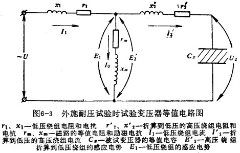
For ease of comparison, based on transformer principles, the test transformer during a withstand voltage test can be simplified to the equivalent circuit shown in Figure 6-3.