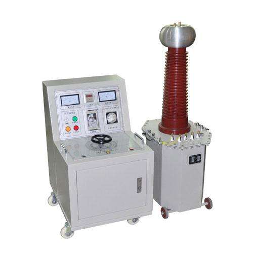
The XGYD series power frequency withstand voltage tester is the most stringent, effective, and direct method for assessing the insulation strength of electrical equipment. It can detect concentrated defects that are more dangerous, playing a decisive role in determining whether electrical equipment can continue to operate, and is an important means to ensure the insulation level of equipment and avoid insulation accidents.
This device is designed according to the latest national power industry standards, and is an advanced performance withstand voltage test equipment, used for insulation strength testing of various electrical products, electrical components, insulating materials, etc., at specified voltages, to assess the insulation level of products, discover insulation defects of the tested object, and measure the ability to withstand overvoltage.
Tools and Raw Materials;
1. The workplace should be free of gases, vapors, chemical dust, and other explosive and corrosive media that seriously affect insulation.
2. Ambient temperature 0~40℃
3. Ambient humidity ≤85% RH (no condensation)
4. Altitude <1000m
Step Method;
Before operating this device, the maximum working current should be calculated based on the capacity and voltage level of different test objects, and the current protector should be adjusted. The test wiring should refer to Figure 1 in this manual or the relevant connection diagram in the test transformer, and the grounding terminal should be properly grounded (take the following withstand voltage test as an example).
Operating Points;
(1) Before the test, understand the test voltage of the test object, as well as other test items and previous test results. If the test object has defects or abnormalities, they should be eliminated before conducting the withstand voltage test.
(2) The test site should be enclosed with barriers or ropes, marked with signs, and supervised by dedicated personnel.
(3) Before the test, the surface of the test object should be wiped clean, and the casing and non-tested windings of the test object should be reliably grounded. If the test object is newly oil-filled equipment, the oil should be allowed to stand for a certain period according to the regulations before raising the voltage. For oil-filled power equipment of 110kV and below, the standing time after filling with oil should be no less than 24 hours; for 220kV and 330kV oil-filled power equipment, the standing time should be no less than 48 hours.
(4) After connecting the test wiring, it should be checked by experienced personnel, and only after confirming no errors can the voltage be raised.
(5) Before raising the voltage, first check whether the voltage regulator is at zero position. Only when the regulator is at zero can the voltage be raised, and it should be done with verbal announcement.
(6) During the voltage raising process, not only should the changes in the voltmeter be monitored, but also the changes in the ammeter and the current of the test object. The voltage should be raised uniformly, not too fast. When the specified test voltage is reached, start timing, and after the time is up, slowly and uniformly lower the voltage. It is absolutely not allowed to trip the power switch without lowering the voltage first.
(7) If abnormal phenomena such as pointer oscillation or abnormal sound, smoke, etc. are found during the test, the voltage should be immediately lowered, the power turned off, and after hanging the grounding wire on the high-voltage side, investigate the cause.
(8) The insulation resistance of the test object should be measured before and after the withstand voltage test.
Operating Steps;
l Connect the wiring correctly according to the test requirements. (Wiring diagram)
l According to the test requirements, set the "time relay" and "overcurrent relay". The overcurrent action setting value = overcurrent relay dial reading × K, where K is the state value of the current multiplier conversion/cut-off switch, respectively 1, 2, ∞. When the switch is in the ×1, ×2 positions, the K values are 1, 2, respectively, and the cut-off position is +∞. The overcurrent relay is set for the primary current value, with a transformation ratio of 25. (Note: Do not use the +∞ gear, as it will cause the transformer to lose overcurrent protection function and lead to equipment damage). l Connect the power supply, turn on the power switch. At this time, the "power indicator (green light)" lights up, indicating that the external power has been introduced. If the "zero position indicator (yellow light)" lights up, it indicates that the voltage regulator is at zero position. If the "zero position indicator" does not light up, rotate the voltage regulator handle counterclockwise until the "zero position indicator" lights up, indicating that voltage regulation operation can be performed. l Press the "start button". At this time, the "working indicator (red light)" lights up, the "power indicator" and "zero position indicator" go out; it enters the power supply state and the voice reminder "Danger, electric shock, please keep away!" is given. l Rotate the voltage regulator handle clockwise at a uniform speed of 2kV/s to the specified withstand voltage value of the test object, and closely watch the ammeter. l Start the "timing switch". When the "timing alarm flashing light" flashes and the "timing alarm" sounds, it indicates that the test time is up; the test is completed. l Rotate the voltage regulator handle counterclockwise until the "zero position indicator" lights up. l Press the "stop button". At this time, the "power indicator" lights up, and the "working indicator" goes out. l Turn off the power switch, unplug the power cord, remove the wiring, and the test is over. l During the voltage raising or withstand voltage process, closely monitor the test object. If short circuit, flashover, breakdown, or overcurrent occurs, the overcurrent relay will operate and cut off the main circuit. At this time, rotate the voltage regulator counterclockwise to zero, cut off the power, investigate the cause, and record in detail. l After the test, lower the voltage, cut off the power, and fully discharge the test object and the test device itself.
Precautions;
When unpacking and accepting, check whether the wiring of the main control circuit is loose and whether the carbon brush of the voltage regulator is in good contact;
l If not used for a long time, measure the insulation resistance with a 500V megohmmeter before use, and the resistance should not be lower than 0.5MΩ; l The power supply voltage should comply with the input voltage value on the nameplate of the box (table); l This box (table) is equipped with overcurrent protection, which has been adjusted to 50% of the rated current at the factory. When used for small loads, it should be reset according to the rated capacity current of the test object; l After use, close the box (table) door cover to keep the interior clean.