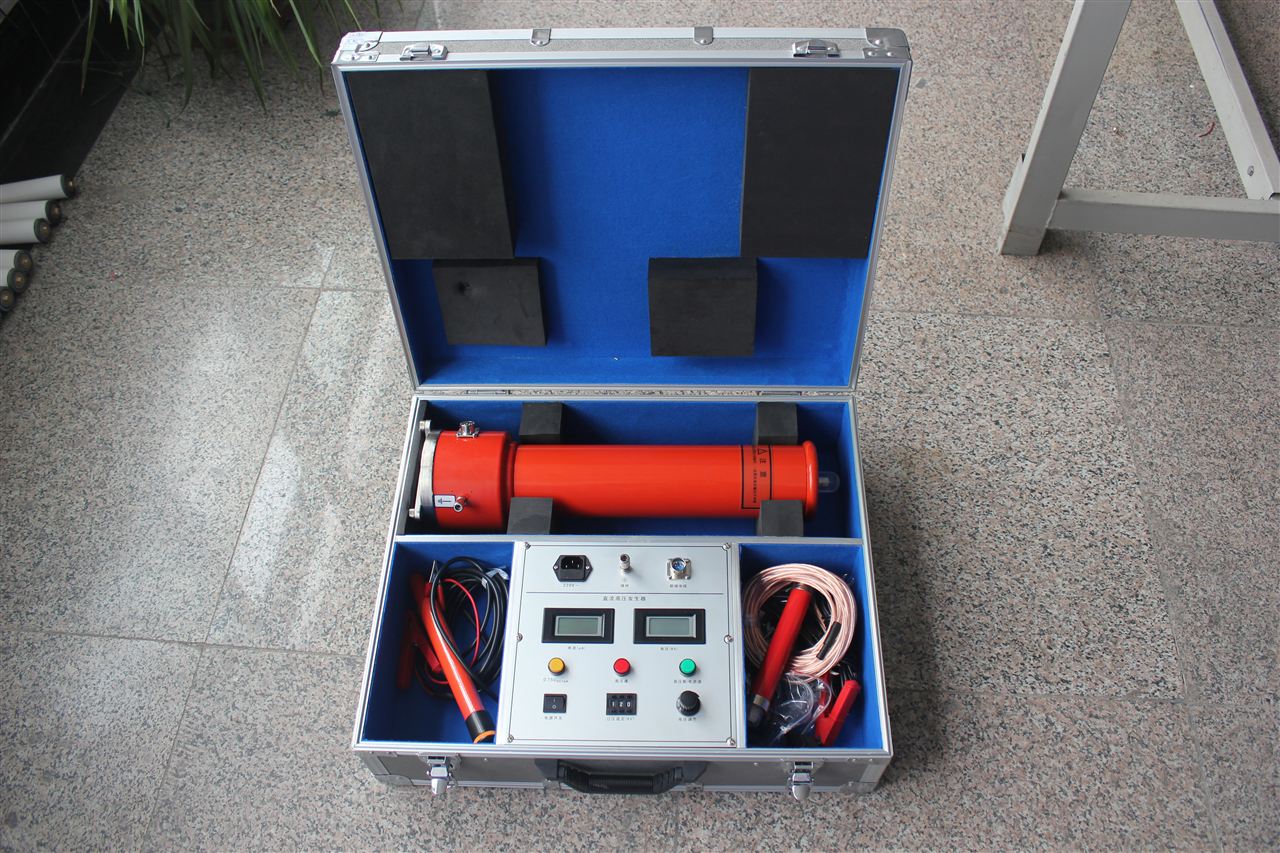
Protection Settings of DC High Voltage Generator
The instrument is equipped with overvoltage protection, overcurrent protection, and internal power protection. Among them, overvoltage protection and overcurrent protection can be set externally, while the power
is determined at the factory and cannot be set externally.
(1) Overvoltage Protection
During the test, if setting is not required, turn the voltage setting knob clockwise to the maximum. At this time, overvoltage protection will activate when the output voltage exceeds the rated value, and the overvoltage protection indicator light will turn on. If you need to set the overvoltage protection value, before the test, you can first not connect the test object, turn the voltage setting knob clockwise to the maximum, then increase the voltage to the desired value according to the aforementioned operation process, then turn the voltage setting knob counterclockwise to the overvoltage protection value, and the overvoltage protection indicator light (yellow) will light up, at which point the overvoltage protection value is set. Then turn off the power switch, use the grounding rod to discharge the high voltage to ground, connect the test object, and the test can be conducted. At this time, if the test voltage exceeds the set value, the high voltage will be automatically cut off, and overvoltage protection will activate.
(2) Overcurrent Protection
During the test, if setting is not required, turn the current setting knob clockwise to the maximum. At this time, overcurrent protection will activate when the output current exceeds the rated value, and the overcurrent protection indicator light (yellow) will turn on. If you need to set the overcurrent protection value, before the test, you can first connect the test object, turn the current setting knob clockwise to the maximum, then increase the current to the desired value according to the aforementioned operation process, then turn the current setting knob counterclockwise to the overcurrent protection value, and the overcurrent protection indicator light (yellow) will light up, at which point the overcurrent protection value is set. Then turn off the power switch, use the grounding rod to discharge the high voltage to ground, connect the test object, and the test can be conducted. At this time, if the test current exceeds the set value, the high voltage will be automatically cut off, and overcurrent protection will activate.
Simple Troubleshooting
1. When the power switch is turned on, the digital display on the control box does not light up. Please check the power connection and all fuses. If any fuse is damaged, replace it with a new one according to the ampere rating marked next to the fuse holder.
2. If the power switch is turned on, the digital display lights up, but the high voltage indicator light (green) does not light up and high voltage cannot be applied. ① The fault display "Return to Zero" light is on. It has not returned to zero. Please turn the high voltage output adjustment knob and fine-tuning knob counterclockwise back to zero until the "Return to Zero" light goes off, then high voltage can be applied. ② The fault display "Other" light is on. There are two phenomena: 1. Ground protection, 2. Disconnection protection. a. The ground wire may not be connected properly, or the ground wire is not reliably grounded. Please connect a reliable ground wire, turn off the power, and restart. b. The cable connecting the control box and the high voltage tower may not be connected properly. After connecting the cable, please turn off the power and restart. Or if the soldered joints at both ends of the cable wire are desoldered, this fault will occur. Please solder the joints at both ends of the cable, turn off the power, and restart. C. A wire connection inside the control box may be desoldered or disconnected. Please re-solder it, turn off the power, and restart. 3. Everything is normal, but protection occurs during the process before reaching the rated output voltage. ① The fault display "Overcurrent" light is on. a. The test object is short-circuited, or the leakage current is too large. b. When the load is a large capacitor, the voltage increase is too fast. Turn off the power, restart, and slow down the voltage increase speed. ② The fault display "Overvoltage" light is on. The overvoltage protection setting knob is not set to the maximum. Please turn it clockwise to the maximum, turn off the power, and restart. 4. When a short circuit occurs under high voltage on the test object, due to the large short-circuit current, it is possible that all fault indicator lights will light up. This is normal. Please eliminate the test object fault and restart. 5. After the test object fault is eliminated, the fault indicator lights are still on, and high voltage cannot be applied. The power switch also serves as the fault protection reset switch. Please turn off the power switch and restart to increase voltage. 6. If you find that the voltage meter reading fluctuates greatly, please check whether the shielding net head of pin 7 of the aviation plug at both ends of the connecting cable and the center shielding wire head are desoldered or disconnected. If disconnected, please solder them well. Definitions 1Rated Output Voltage Under specified working conditions, when the high voltage output terminal of the DC high voltage generator is connected to the test object through a current limiting resistor, and when the rated output current passes through the test object and the DC high voltage ripple meets the requirements, the maximum DC voltage is called the rated output voltage. 2Rated Output Current Under specified working conditions and specified continuous operation time, the maximum current that the DC high voltage generator can output when the output voltage and its ripple meet the requirements is called the rated output current. 3Rated Output Power When the rated output voltage and rated output current appear simultaneously, the product of these two rated values is called the rated output power. 4DC High Voltage Ripple Ripple refers to the periodic fluctuation of the arithmetic mean value of DC high voltage. The ripple amplitude is half of the difference between the maximum and minimum values. The ripple factor is the ratio of the ripple amplitude to the arithmetic mean value. 5DC High Voltage Random Fluctuation DC high voltage random fluctuation is the fluctuation of the DC high voltage output terminal due to the influence of the AC power grid voltage. The random fluctuation amplitude refers to the random change of the arithmetic mean value of DC high voltage. 6DC High Voltage Drift DC high voltage drift refers to the drift value of DC high voltage within a certain period of time when the power supply voltage is constant, under resistive load conditions, and when the DC high voltage regulator is placed at the rated voltage position.