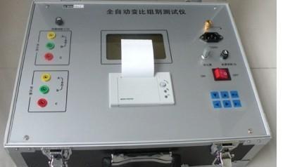
The transformer ratio is one of the important parameters of a transformer, and its variation is closely related to changes in the transformer windings. The measurement of the transformer ratio, i.e., the measurement of the transformer voltage ratio, is conducted to check whether the number of turns in each winding meets the design and operational requirements, hence it is also called the turns ratio test. The rated voltage ratio of the high-voltage to low-voltage side of a transformer is often a fraction (or expressed as a decimal), so it is necessary to round to the nearest integer number of turns. This inevitably causes a slight deviation between the voltage ratio and the turns ratio. This error must be controlled during the production process to keep it within allowable limits, and the transformer ratio needs to be tested during production.
The hardware design of the tester mainly includes the following functional modules:
1. Test power supply generation module
This module is mainly used to generate the primary side power supply during the transformer ratio test, consisting mainly of a waveform generation circuit and a power amplification circuit.
2. Data acquisition and processing system
This system completes the acquisition and processing of the AC voltage output from the secondary side of the tested transformer, mainly consisting of a gain control circuit, an AC/AD conversion circuit, and a voltage-to-frequency conversion circuit.
3. Keyboard and display module
This system has good human-machine interaction functions. During the test, the LCD display module mainly shows the current working status of the system. When the test ends, it displays the results of this test. Through the keys, functions such as selection of the type of transformer under test, starting or terminating the test can be achieved. This system mainly has the following function keys: 0-9 numeric keys, decimal point, up/down/left/right selection keys, reset key, confirm key, and cancel key.
4. Communication module
The system includes a serial communication module that enables information exchange between the tester and a PC. Users can remotely start and terminate the transformer ratio test via the PC, and can also request the tester to upload test data.
5. Watchdog protection circuit
The watchdog timeout delay reset circuit (hereinafter referred to as the watchdog circuit) can not only ensure that the microcontroller system generates a reliable reset pulse when powered on, but also reset the microcontroller when it crashes.
Overall software design of the tester
This software is designed for testing the transformer ratio of transformers with special connection methods, mainly completing functions such as waveform generation, data acquisition, data upload, and transformer ratio calculation during the test. This transformer ratio tester has two working modes: independent detection mode and remote operation control mode. After the system starts successfully, the entire system runs in an idle state. When it receives a manual start detection key installed on the housing or a command from the host PC, the tester is activated and enters the corresponding processing program. The manual mode is established to give the tester a certain degree of independence, making it convenient for portable use. When the host computer is unavailable or remote operation control cannot be achieved for other reasons, the staff can complete a test without the host computer by simply pressing the manual detection key.
l) When the manual detection key is pressed, the corresponding flag is set, and the measurement object key is detected to set the relevant parameter values, and the system starts the transformer ratio test. After the detection is completed, the transformer ratio of the tested transformer is calculated and sent to the LCD for display. After all measurements are completed, the detection processing subroutine is exited, and the system enters the idle state.
2) When the system is in remote operation control mode, the lower computer receives instructions from the upper computer, executes corresponding operations, and starts or terminates a test. After a test is completed, the lower computer can upload relevant test result information to the upper computer to achieve remote calculation of data parameters. The main functional modules of the software are shown in Figure 1. The software part of the transformer ratio measurement system is mainly divided into modules such as the main program, keyboard and display subroutine, waveform generation subroutine, communication interrupt service subroutine, and transformer ratio and ratio error calculation subroutine.
The transformer ratio is an important parameter of a transformer, and its variation is closely related to changes in the transformer windings. Due to the special connection method of such transformers, the commonly used transformer ratio measuring instruments cannot be directly applied to the transformer ratio measurement of such transformers, so studying a ratio tester for such transformers has certain practical significance.