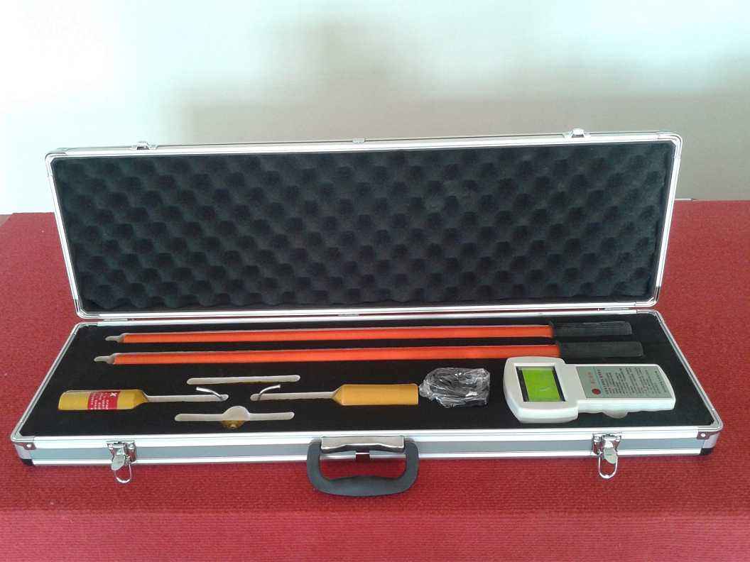
The YTC6220 type high-voltage wireless phase verifier includes three components that are electrically disconnected from each other: two transmitters (see Figure 1) and a receiver (see Figure 2). The transmitters are equipped with electrodes that can be connected to the tested wires. The electrodes are hook-shaped to hang onto the wires. During measurement, the two transmitters are respectively connected to the detection lines. These electrodes serve as transmitting antennas. The ends of the transmitters should be connected to insulated operating rods.
The receiver is a handheld instrument with a built-in antenna for receiving digital signals sent by the transmitters. After receiving the phase signals transmitted by the transmitters, it analyzes and processes them, and then displays the frequency, voltage waveform, and phase difference on the LCD.
The transmitter is a combined unit of a voltage detector and a transmitter. It first determines whether the line is live, and then sends a signal about the phase of the conductor. The receiver obtains the signal sent by the transmitter and then notifies the user during testing that the conductors are in phase.
In use, first contact the transmitter devices used for all lines with the two lines respectively, and confirm they are live by emitting a buzzing sound and flashing light. Then place transmitter 1 at one end of the open circuit point, and transmitter 2 successively on each phase line at the other end of the open circuit point, until finding the line that is in phase with the conductor where transmitter 1 is located. At this time, the receiver's LCD displays the frequency, voltage waveform, and phase difference on the two lines.